I am Mohit Ahuja and I love to build and work on robots. I am fully passionate and dedicated towards exploring
various challenges in the field of Robotics, Computer Vision and Deep Learning. I am keen to collaborate and
work with robotics researchers across the globe so that I can help solving interesting problems and at the
same time, can develop deeper understanding of various innovative technologies linked with robotics. Some
of my research interests, but not limited to, are Control & Perception for mobile robots, Deep learning for
visual recognition and SLAM & Probabilistic robotics.
Mohit Kumar Ahuja
Martin Linges vei 25
1364 Fornebu,
Oslo, Norway.
+47-94162049
MohitKumarAhuja@gmail.com
Erasmus Master in Computer Vision and Robotics(VIBOT) • August 2018
The master course aims to provide qualifications for entry into the professions in the area of robotics, computer vision,
image processing and medical imaging either in public laboratory or private research company. We are required to cover the areas of studies below,
1. Basis of signal and image processing: software, hardware
2. Tools and methods of computer vision: compression, segmentation, real-time, shape recognition, 3D vision, etc.
3. Robotics: fundamentals, control and programming for robot autonomy and intelligence.
4. Medical imaging: biologic basis, infrared imagery, X-Ray and ultrasound imagery.
5. Research training period or a vocational training period.
Bachelors in Electronics & Communication Engineering• March 2014
This subject area offers multidisciplinary teaching in electronics in all its aspects as well as its applications. The teaching provides a basis in analogue and digital electronics, which is necessary for an understanding of the study of various electronics systems. This allows students to acquire vital knowledge in computer science, mathematics and physics that is complementary to the teaching in electronics.
3 Years Polytechnic course in Electronics & Communication Engineering• June 2011
This is 3 year polytechnic course in Electronic communications engineering in which the utilization of science and math applied to practical problems in the field of communications is taught. Electronic communications engineers engage in research, design, development and testing of the electronic equipment used in various communications systems. It is due to electrical engineers that we enjoy such modern communication devices as cellular telephones, radios and television.
Research Intern • Feb 2018 - Current
My Master thesis is being supervised by two Prfessors from two different Labs, one is (CNRS-I3S Lab) and the second is (CNRS-Le2i Lab). I3S laboratory is the largest information and communication science laboratory in the French Riviera. I am working in Aerial Robotics department of team (SIS) on project "Vision-Based Control using Deep Learning of UAV".
Research Intern • June 2017 - Sep 2017
Laboratory of Computer Science, Robotics, and Microelectronics of Montpellier is a cross-faculty research entity of the University of Montpellier and the National Center for Scientific Research. And I am working in Surgical Robotics department on project "Modalise and Localise the tip of flixible instruments like endoscopes using Machine Learning algorithm".
Co-Founder • January 2015–August 2016
Anand Robotix is a firm which provides Education to students about Robotics, Artificial Intelligence, Embedded Systems and Image Processing. And my work was handling industrial embedded projects, delivering robotics workshops to colleges/industries of India.
Associate Engineer • September 2014 - January 2015
Ericsson is a multinational networking and telecommunications equipment and services company. The company offers services, software and infrastructure in information and communications technology (ICT) for telecommunications operators, traditional telecommunications and Internet Protocol (IP) networking equipment, mobile and fixed broadband, operations and business support services, cable television, IPTV, video systems, and an extensive services operation. My work was to Analysing the network performance and ensure 100% Network availability by supervising all critical, major and minor alarms and providing solutions.
Research Engineer Trainee • December 2013 - June 2014
Robosapiens Technologies Pvt. Ltd. is India's leading end to end and eminent training provider company, which focuses on education solutions, covering Robotics Education and doing Research & development in Robotics, embedded Systems, Quadcopter etc. My work was to handle industrial projects.
Training • December 2012 - January 2013
S.T Robotix is a training institute where they provide training to engineering students and make them familier with hardware. I learned alot of things there like PCB Designing, Embedded system using 8051 microcontroller and Robotics.
Intern • December 2011 - January 2012
Rayat Institute of Engineering and Information technology was my college from where I did my bachelor's Degree in discipline Electronics and communication engineering. There I was selected for a 2 months internship where I learned image processing using Matlab.
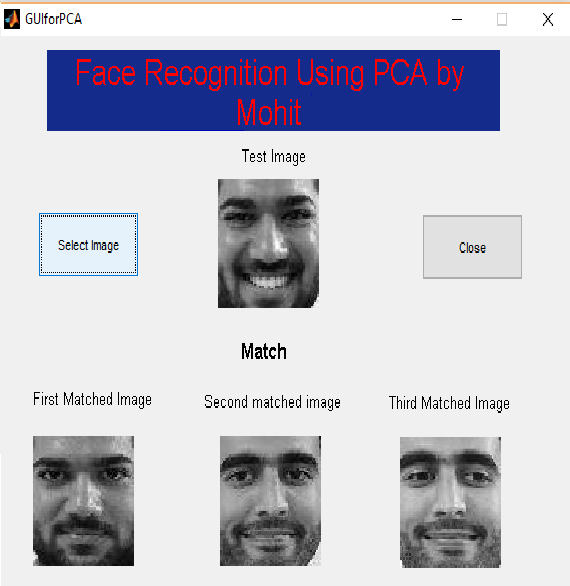
The aim of this project was build a face recognition system based on eigenfaces using a small face dataset. The project is divided in two main parts. 1) Normalization of faces. 2) PCA (Principal Component Analysis) based face recognition system. A friendly, interactive graphical user interface provides simple control and outputs matched image for a given test image.
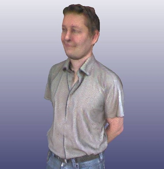
Applied Mathematics, Dr. Sidibe DesireThe main objective of this project was to develop a 3D human body scanner software able to fully interface with a scanner rig composed of a turning table and a stationary depth sensor. The software developed is aimed to perform full body scan under 90 seconds. A friendly, interactive graphical user interface provides simple control and outputs watertight mesh results that can be used mainly but not limited to 3D printing.
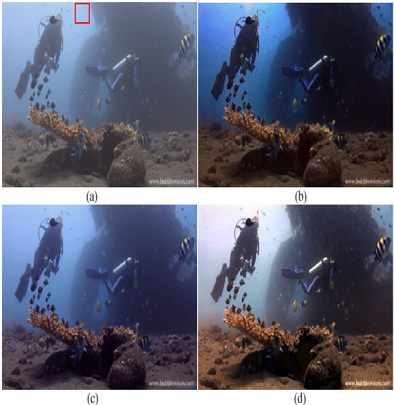
Software Engineering, Dr. Yohan FougerolleThe main objective of this project was to develop a software able to fully Dehaze the image captured underwater using the wavelength compensation and dehazing method. Because capturing clear images in underwater environments is an important issue of ocean engineering The effectiveness of applications such as underwater navigational monitoring and environment evaluation depend on the quality of underwater images. Capturing clear images underwater is challenging, mostly due to haze caused by color scatter in addition to color cast from varying light attenuation in different wavelengths
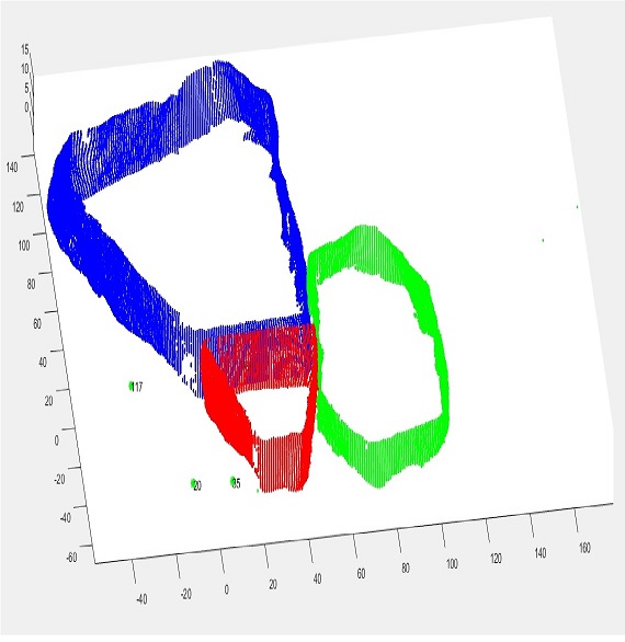
Image Processing, Dr. Sidibe DesireThe main objective of this project was to obtain a new cloud of points by merging the 2 clouds • 1st difficulty: One is full for the second 10% of the points are missing • 2nd difficulty: for each cloud 10% of the points are missing • 1st step: on a classical geometrical volume • 2nd step: on real scans
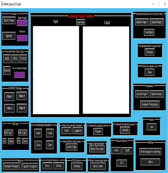
Applied Mathematics, Dr. Eric FauvetThe main objective of this project was to learn MATLAB as a powerful computer vision tool. Also to learn one of the most important computer vision open source libraries, OpenCV. And to test and implement some important computer vision algorithms.. The complete toolbox was implimented in both Matlab as well as in C++. You can see the report and the problem statement down.
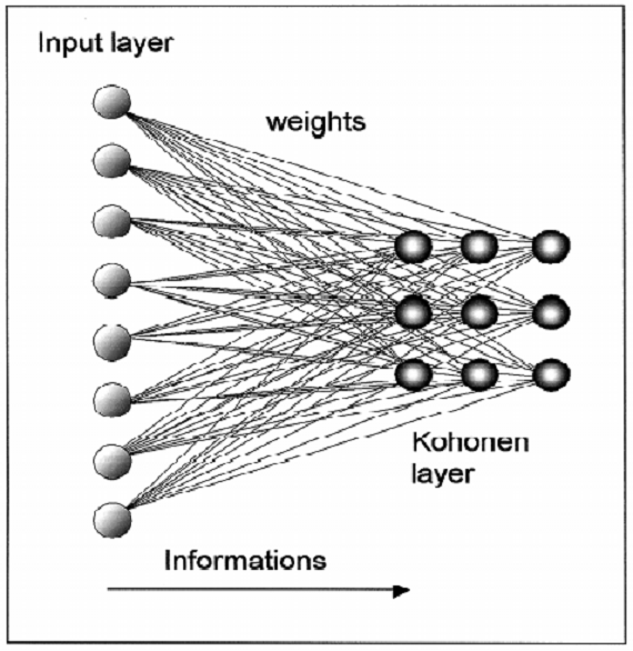
Visual Preception, Dr. Abd El Rahman SHABAYEKThe main objective of this project was to construct a kohonen network and then use that kohonen network. for classification of patient from mixed data of healthy people and non-healthy people.
Visual Preception, Dr. Elizabeth ThomasThe main objective of this project was to develop an interface GUI in MATLAB to do some important functions like: segmentation of tumor region (only ZP, ZT, ZC, and the tumor region ). And showing a 3D representation of the prostate gland, Showing a 3D representation for PZ and CZ, Showing a 3D representation of the tumor region, etc, etc.
Medical Image Analysis, Dr. Christian Mata MiquelThe main objective of this project was video-based human action detection, which has recently been demonstrated to be very useful in a wide range of applications including video surveillance, tele-monitoring of patients and senior people, medical diagnosis and training, video content analysis and search, and intelligent human computer interaction. We implemented 3 methods of feature extraction which are: Spatial temporal Interest point(STIP), SIFT, Optical Flow. Out of all, Optical flow gave us best result with an accuracy of 60%. Actions can be characterized by spatiotemporal patterns. Similar to the object detection, action detection finds the reoccurrences of such spatiotemporal patterns through pattern matching. Compared with human motion capture, which requires recovering the full pose and motion of the human body, the task of action detection only requires detecting the occurrences of a certain type of actions.
Scene Segmentation & Interpretation, Dr. Sidibe DesireThe main objective of this Internship was to desig a kinematic model for the system, Compensating Dead-Band, Compensating Backlash, Find location of tip in real world using machine learning algorithm.
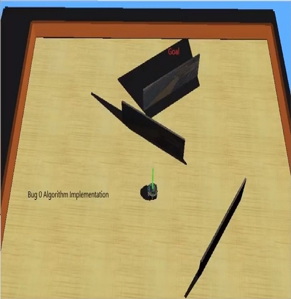
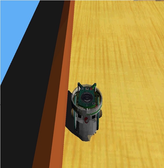
The main objective of this project was Implement Bug 0 Algorithm on E-Puck Robot. In this project we have to set a goal anywhere in the plane and there might be or might not be obstacles in the path. And the Robot have to first identify the Goal in comparative to his own location and then start moving towards it and it should turn according to the angle of rotation required for facing towards goal. If there is any obstacle in between robot and the goal, The Robot should follow the obstacle till he see its goal again (or till the obstacle is finished). The robot should calculate the angle of rotation again to face towards the goal and then start moving towards it and once the robot reaches the destination (Goal) it should stop.
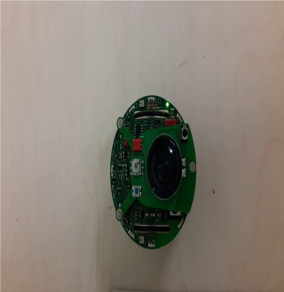
Autonomous Robotics, Dr. Xevi CufíThe main objective of this project was to compute odometry and to perform different tasks on E-Puck Robot. Like: Converting the measures of the encoders to distances travelled by the left and right wheels. Compute now the odometry. Finding the error of the odometry in a translation only movement. Finding the error of the odometry in a rotation only movement. Finding the error of the odometry in a combined movement.
Autonomous Robotics, Dr. Xevi CufíThe main objective of this project was to code the E-Puck Robot to detect the wall at 2cm distance from the wall and then start following it by maintaining the 2cm distance. It will be more clear from the Videos, link of the videos are mentioned below.
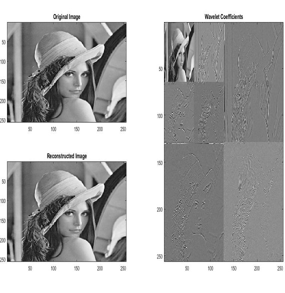
Autonomous Robotics, Dr. Xevi CufíThe main objective of this project was to Develop a Matlab function for computing the J-level wavelet
transform of an NxN image (assume N is a power of 2) and to Develop another Matlab function for
computing the inverse J-level wavelet transform of an NxN array of wavelet coefficients. And then
test it by adding filters and then test it agaain by adding some Noise to it.
There are two main steps in Wavelet Transformation which are:
1. Decomposition
2. Reconstruction
So, in the decomposition part we decompose the signal using two Filters:
1. High Pass Filter – G0
2. Low Pass Filter – H0
and, the reconstruction part also consists of two Filters:
1. High Pass Filter – G0
2. Low Pass Filter – H0.
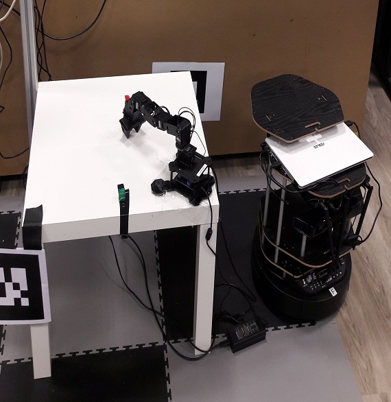
The motto of the project was to gain experience in the implementation of different robotic algorithms
using ROS framework. The hardware we were using was a Turtle Bot 2 with a Kobuki base as our robotic
hardware platform with Kinect 1 which was an RGB-D sensor. We were using ROS as a software framework.
1. The first step of task was to build a map of the environment and navigate to the desired location on
the map.
2. Next, we have to sense the location of the marker (e.g. AR marker, colour markers etc) in
the map, where there is pick and place task, and autonomously localise and navigate to the desired
marker location..
3. After reaching to the desired marker location, we have to precisely move towards the specified
location based on visual servoing.
4. At this location, we have a robotic arm which picks an object (e.g a small cube) and places on
our turtlebot (called as pick and place task).
5. After, the pick and place task, again the robot needs to find another marker, which specifies
the final target location, and autonomously localise and navigate to the desired marker
location, which finishes the complete task of the project.
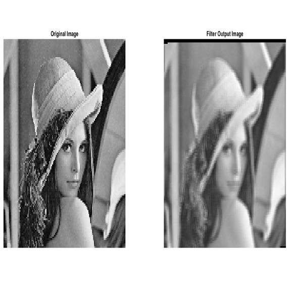
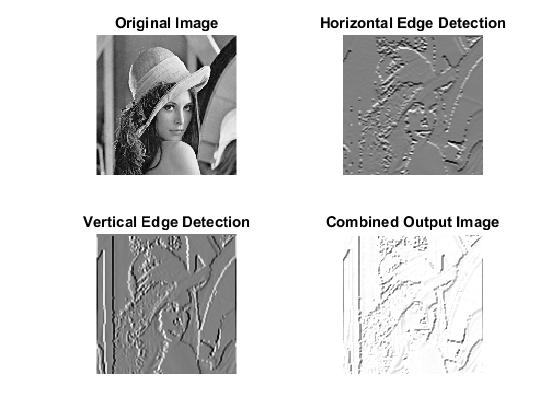
The goal is to process the input data flow (corresponding to lena image) using a 2D filter.
Two main tasks are expected:
1. The design and the validation of a customizable 2D filter (filter IP).
2. The implementation on a Nexys4 evaluation board of the 2D filter. The filter IP implementation
should be included in a reference design (furnished by teacher) to ease the integration.
The filter IP could be split into two main parts: the memory cache which aims to be temporarily
stored the data flow before filtering and the processing part. The cache memory designed for
simultaneous pixel accesses enables a 3x3 pixel neighbourhood to be accessible in one clock cycle.
The structure is based on flip-flop registers and First-In-First-Out (FIFO) memory.
The goal of this Visual Tracking module is to learn about, and, more importantly, to learn how to use
basic tracking algorithms and evaluate their performances. We will start with a very simple and
effective technique called Background Subtraction which can be used to initialize the tracker,
i.e. to find the target’s position in the first frame of a sequence, or to track the target
through the entire sequence..
Background subtraction (BS) is widely used in surveillance and security applications, and serves as a
first step in detecting objects or people in videos. BS is based on a model of the scene
background that is the static part of the scene. Each pixel is analyzed and a deviation from the
model is used to classify pixels as being background or foreground.
As an example, you can see the car sequence in file “back_sub_car.m”. We want to track the car
in this sequence. We first needed to detect the car’s position in the first frame of the sequence,
or provide that location manually. If we have a model B of the static part of the scene, then
moving objects can be detected in an image I, just by taking the difference I - B.
The goal of this Visual Tracking module is to learn about, and, more importantly, to learn how to use
basic tracking algorithms and evaluate their performances. After Background Subtraction, we will
now use a very effective technique for real-time tracking called Mean-Shift. Mean-Shift is a
deterministic algorithm, as opposed to probabilistic ones, which solves the data association
problem (matching) in a very effective way.
Mean-Shift (MS) Mean-Shift (MS) is widely known as one of the most basic yet powerful tracking algorithms.
Mean- Shift considers feature space as an empirical probability density function (pdf). If the
input is a set of points then MS considers them as sampled from the underlying pdf. If dense
regions (or clusters) are present in the feature space, then they correspond to the local maxima
of the pdf. For each data point, MS associates it with the nearby peak of the pdf.
As an example, you can see the car sequence in file “Mean_Shift_Tracking.m”. We want to track
the car in this sequence. We first needed to define the initial patch of the car in the first
frame of the sequence. And then the moving car patch will be estimated by using the Bhattacharya
coefficient and the weights corresponding to the neighboring patches. It will be deeply explained
in the report.
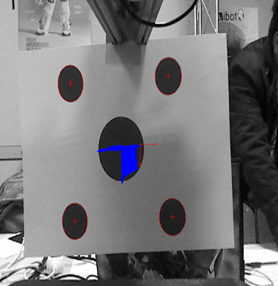
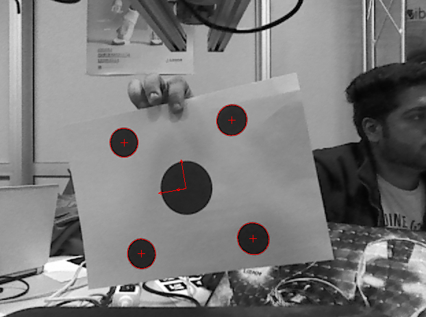
We have done dot detection, tracking, computing pose and virtual visual servoing using VISP library.
We had seen great advantages of this library as we can track and detect using a single line of
code and the data structures defined for holding data are well defined and the class and methods
used in the library are well documented with many examples. We found it's easy to use this
library for visual servoing in the context of our tasks.
In this, we assumed a virtual free flying robot and also set a pose for the free flying robot as cMo as
we calculated in task 2. We also set the desired pose of robot cdMo as below:
vpHomogeneousMatrix cdMo(0, 0, 0.75, 0, 0, 0); // We only gave the translation in z-axis.
So as we need to move the robot we need a vpServo object and a velocity to move it, computed
using control law. Here we are considering the 4 points as our features. As we already have
normalized coordinates of dots tracking we can define four desired features vpFeaturePoint using
create method of vpFeatureBuilder class. As we know the point coordinates in object frame, the 4
features described are the projection of object four points in image, for current pose cMo. So,
we apply frame change on each vpPoint and we apply perspective projection using the projection
method and we update the feature. These feature points are added to the vpServo object and
control law is computed to get the 6-vector velocity. Then we can update the camera pose using
this velocity and we can get the new cMo from the robot camera. The above process is run in a
loop of iterations so that the initial pose reaches the desired pose.
We have done Intensity Based Visual Servoing by computing velocities for the robot using Control
Law by VISP library. We had seen great advantages of this library as we can track and detect
using a single line of code and the data structures defined for holding data are well defined
and the class and methods used in the library are well documented with many examples. We found
it's easy to use this library for visual servoing in the context of our tasks.
There was an error using the function “vpImageio”. So, we used OpenCV function “Imread” to read
the image. For Intensity-Based Visual Servoing (InBVS), we followed the following sequence:
1. We gave the current pose of the camera (cMo) as well as the desired pose of the camera (cdMo).
The only difference in current and desired pose is the rotation. The translation has not been
changed.
2. We have to set the Robot Position using robot.setPosition(cMo).
3. We loaded the image and started acquiring the images using getImage() function of
“vpImageSimulator”. But before getting image, we have to set the position of the camera by
giving the homogeneous matrix (cMo) setCameraPosition function.
4. We acquired images from both current and desired pose and then computed the difference between
both using imageDifference function of “VpImageTools” object. And then displaying all the three
images.
5. We created two objects named vpFeatLumCur for current image and vpFeatLumDes for desired image,
these objects are made from class “vpFeatureLuminance”. We initialized both using init() function
and once giving the parameters of current image and secondly giving the parameters of the desired
image.
6. Then we set the camera parameters and built two features, one for current image and one for
desired image using buildfrom(). The visual feature for current image is computed every time but
the visual feature of desired image is only computed once.
We have done 3D model object detection, tracking, computing pose using VISP library. We had seen great
advantages of this library as we can track and detect using a single line of code and the data
structures defined for holding data are well defined and the class and methods used in the
library are well documented with many examples. We found it's easy to use this library for
visual servoing in the context of our tasks.
The Image acquisition and initialization of tracker is done by the following sequence:
1. We need to start Kinect for this we used MyFreenectDevice object, as we acquired 50 frames we
stopped streaming to see the initial object to select points.
2. We have to replace the 3D points in “Box.cao” file with the measured 3D points of Box which we
have to track in video. The distances of tracked object are given in “Box.cao” file.
3. We have to edit the faces in the “Box.cao” file with accordance to the sequence of 3D corner
points we gave above.
4. On the last image grabbed, we will right click to provide 4 points of corners but those 4
points should not be on the same frame and we have to define those points in the “Box.init” file.
5. When we will have 4 points, press left click to validate. And it will start tracking the box in
every frame. Here, camera parameters are required to get the object in image frame which is used
to display the tracked object correctly.
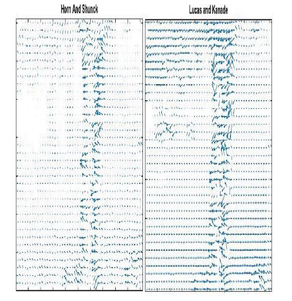
The goal of this project was to get familiarized with optical flow problem's by implementing
Horn-Schunck and Lucas-Kanade methods will be applied to image stabilization problem.
The Horn–Schunck method of estimating optical flow is a global method which introduces a global
constraint of smoothness to solve the aperture problem.
In computer vision, the Lucas–Kanade method is a widely used differential method for optical flow
estimation developed by Bruce D. Lucas and Takeo Kanade. It assumes that the flow is essentially
constant in a local neighbourhood of the pixel under consideration, and solves the basic optical
flow equations for all the pixels in that neighbourhood, by the least squares criterion.
By combining information from several nearby pixels, the Lucas–Kanade method can often resolve the
inherent ambiguity of the optical flow equation. It is also less sensitive to image noise
than point-wise methods. On the other hand, since it is a purely local method, it cannot
provide flow information in the interior of uniform regions of the image.
You can send me mail if you have any query also I am all the time available via phone but I don't
prefer phone calls, so please send me an email untill its too urgent ;)
Your mail will be replied within few hours!